
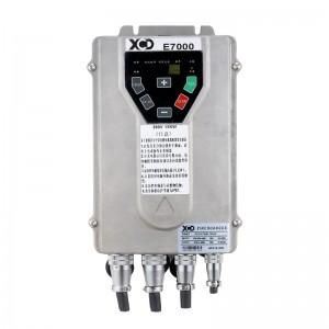
1. The working principle of the fully-controlled High Protection Universal Vector Inverter XCD-E7000 It is the main circuit of the full-bridge inverter with single-phase output that is usually used, and the AC components use IGBT tubes Q11, Q12, Q13, and Q14. And by the PWM pulse width modulation to control the conduction or cut-off of the IGBT tube.
When the inverter circuit is connected to the DC power supply, firstly, Q11 and Q14 are turned on, and Q1 and Q13 are turned off, and the current is output from the positive pole of the DC power supply. to the negative pole of the power supply. When Q11 and Q14 are turned off, Q12 and Q13 are turned on, and the current flows from the positive pole of the power supply to the negative pole of the power supply through Q13, the inductance of the primary coil 2-1 of the transformer to Q12. At this time, on the primary coil of the transformer, positive and negative alternating square waves have been formed. Using high-frequency PWM control, two pairs of IGBT tubes are alternately repeated to generate AC voltage on the transformer. Due to the action of the LC AC filter, the output terminal forms a sine wave AC voltage. When Q11 and Q14 are turned off, in order to release the stored energy, diodes D11 and D12 are connected in parallel at the IGBT to return the energy to the DC power supply.
2. Working principle of half-controlled inverter: The half-controlled inverter uses thyristor elements. The main circuit of the improved parallel inverter is shown in Figure 4. In the figure, Th1 and Th2 are thyristors that work alternately. If Th1 is triggered and turned on first, the current flows through Th1 through the transformer. At the same time, due to the inductive effect of the transformer, the commutation capacitor C is charged to the power supply voltage that is twice as large. According to Th2 is triggered and turned on, because the anode of Th2 is reverse biased, Th1 is turned off and returns to the blocking state. In this way, Th1 and Th2 are commutated, and then the capacitor C is charged in reverse polarity. In this way, the thyristors are triggered alternately, and the current flows alternately to the primary of the transformer, and alternating current is obtained at the secondary of the transformer.
In the circuit, the inductance L can limit the discharge current of the commutation capacitor C, prolong the discharge time, and ensure that the circuit turn-off time is greater than the turn-off time of the thyristor, without the need for a capacitor with a large capacity. D1 and D2 are two feedback diodes, which can release the energy in the inductance L and send the remaining energy back to the power supply to complete the energy feedback.
Post time: Feb-14-2023